- 您现在的位置:买卖IC网 > Sheet目录868 > LTM4607IV#PBF (Linear Technology)IC BUCK/BOOST SYNC ADJ 5A 141LGA
�� �
�
�LTM4607�
�APPLICATIONS� INFORMATION�
�0.6�
�0.4�
�0.2�
�1.5μH�
�2.5μH�
�3.3μH�
�4.7μH�
�V� OUT� =� 12V�
�?� =� 400kHz�
�to� achieve� the� same� output� ripples� as� the� buck� mode.� If�
�assuming� that� the� ESR� dominates� the� output� ripple,� the�
�output� ripple� is� as� follows:�
�Δ� V� OUT(P-P)� =� ESR� ?� I� L(MAX)�
�If� a� total� low� ESR� about� 5m� is� chosen� for� output� capaci-�
�tors,� the� maximum� output� ripple� of� 70mV� occurs� at� the�
�input� voltage� of� 5V� with� the� peak� inductor� current� at� 14A.�
�0�
�5�
�6�
�7�
�8�
�9�
�10�
�11�
�12�
�An� RC� snubber� is� recommended� on� SW1� to� obtain� low�
�switching� noise,� as� shown� in� Figure� 17.�
�INPUT� VOLTAGE� V� IN� (V)�
�4607� F04�
�Wide� Input� Mode� Operation�
�R� SENSE� =�
�2� ?�
�+� Δ� I� L�
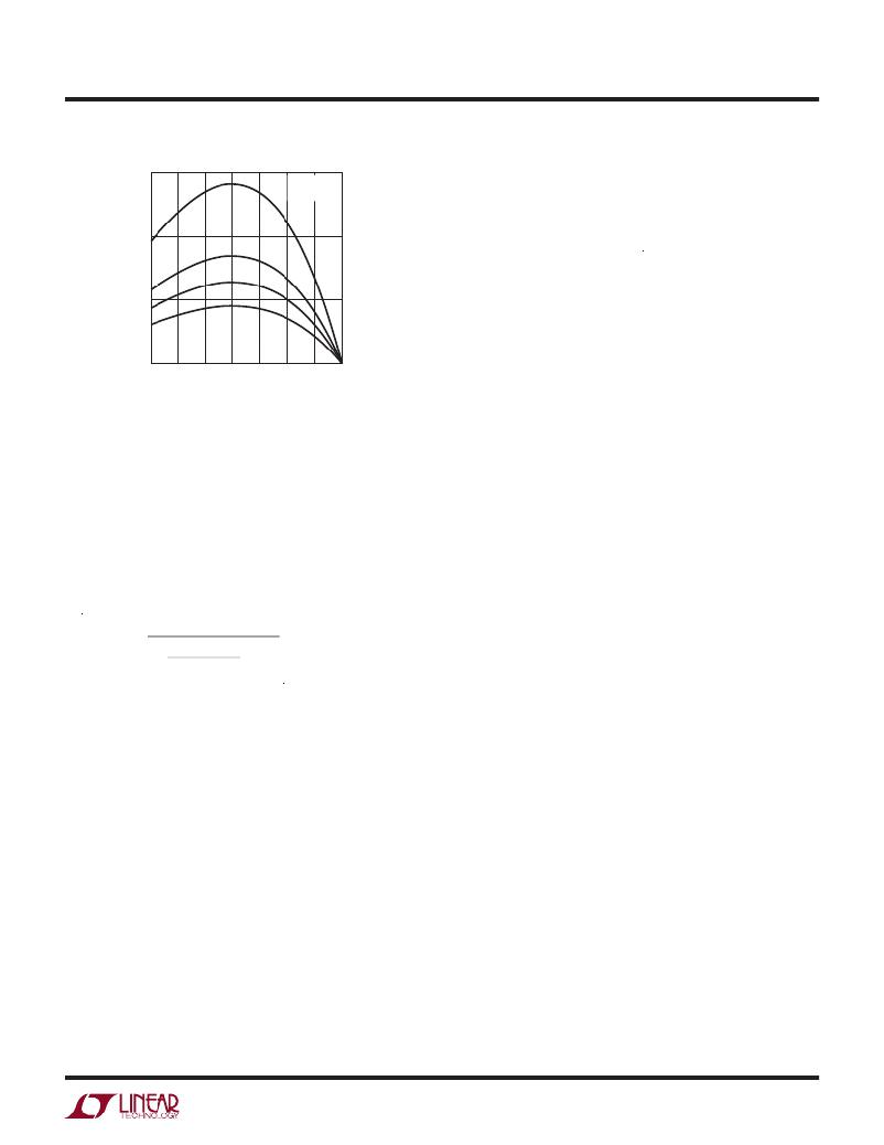
�Figure4.CurrentRippleRatioatDifferentInputsforBoostMode�
�Figure� 4� shows� the� current� ripple� ratio� at� different� input�
�voltages� based� on� the� inductor� values:� 1.5μH,� 2.5μH,�
�3.3μH� and� 4.7μH.� If� we� need� 30%� ripple� current� ratio� at�
�all� inputs,� the� 3.3μH� inductor� can� be� selected.�
�At� boost� mode,� sensing� resistor� selection� is� based� on�
�the� maximum� input� current� and� the� allowed� maximum�
�sensing� threshold� 160mV.�
�2� ?� 160mV�
�P�
�η� ?� V� IN(MIN)�
�Consider� the� safety� margin� about� 30%,� we� can� choose�
�the� sensing� resistor� as� 7mΩ.�
�For� the� input� capacitor,� only� minimum� capacitors� are�
�needed� to� handle� the� maximum� RMS� current,� since� it�
�is� a� continuous� input� current� at� boost� mode.� A� 100μF�
�capacitor� is� only� needed� if� the� input� source� impedance� is�
�compromised� by� long� inductive� leads� or� traces.�
�Since� the� output� capacitors� at� boost� mode� need� to� filter�
�the� square� wave� current,� more� capacitors� are� expected�
�If� a� wide� input� range� is� required� from� 5V� to� 36V,� the� mod-�
�ule� will� work� in� different� operation� modes.� If� input� voltage�
�V� IN� =� 5V� to� 36V,� V� OUT� =� 12V� and� ?� =� 400kHz,� the� design�
�needs� to� consider� the� worst� case� in� buck� or� boost� mode�
�design.� Therefore,� the� maximum� output� power� is� limited�
�to� 60W.� The� sensing� resistor� is� chosen� at� 7mΩ,� the� input�
�capacitor� is� the� same� as� the� buck� mode� design� and� the�
�output� capacitor� uses� the� boost� mode� design.� Since� the�
�maximum� output� ripple� normally� occurs� at� boost� mode�
�in� the� wide� input� mode� design,� more� inductor� ripple� cur-�
�rent,� up� to� 150%� of� the� inductor� current,� is� allowed� at�
�buck� mode� to� meet� the� ripple� design� requirement.� Thus,�
�a� 3.3μH� inductor� is� chosen� at� the� wide� input� mode.� The�
�maximum� output� ripple� voltage� is� still� 70mV� if� the� total�
�ESR� is� about� 5mΩ.�
�Additionally,� the� current� limit� may� become� very� high� when�
�the� module� runs� at� buck� mode� due� to� the� low� sensing�
�resistor� used� in� the� wide� input� mode� operation.�
�Safety� Considerations�
�The� LTM4607� modules� do� not� provide� isolation� from� V� IN�
�to� V� OUT� .� There� is� no� internal� fuse.� If� required,� a� slow� blow�
�fuse� with� a� rating� twice� the� maximum� input� current� needs�
�to� be� provided� to� protect� each� unit� from� catastrophic� failure.�
�15�
�For� more� information� www.linear.com/LTM4607�
�4607fc�
�发布紧急采购,3分钟左右您将得到回复。
相关PDF资料
LTM4608AEV#PBF
IC BUCK SYNC ADJ 8A 68LGA
LTM4608IV#PBF
IC DC/DC UMODULE 8A 68-LGA
LTM4609IV#PBF
IC BUCK/BOOST SYNC ADJ 4A 141LGA
LTM4612IV#PBF
IC BUCK SYNC ADJ 5A 133LGA
LTM4613MPV#PBF
IC UMODULE DC/DC 8A 133-LGA
LTM4614IV#PBF
IC UMODULE DC/DC DUAL 4A 144LGA
LTM4615IV#PBF
IC SWIT REG BUCK 4A ADJ 144LGA
LTM4618IV#PBF
IC DC-DC UMODULE BUCK 6A 84-LGA
相关代理商/技术参数
LTM4607IVPBF
制造商:Linear Technology 功能描述:Conv DC-DC Step Up Step Down
LTM4607IV-PBF
制造商:LINER 制造商全称:Linear Technology 功能描述:36VIN, 24VOUT High Effi ciency Buck-Boost DC/DC μModule
LTM4607V
制造商:LINER 制造商全称:Linear Technology 功能描述:36VIN, 24VOUT High Effi ciency Buck-Boost DC/DC μModule
LTM4608
制造商:LINER 制造商全称:Linear Technology 功能描述:Low VIN, 8A DC/DC μModuleTM with Tracking, Margining, and Frequency Synchronization
LTM4608_1
制造商:LINER 制造商全称:Linear Technology 功能描述:Low VIN, 8A DC/DC Module Regulator with Tracking, Margining, and Frequency Synchronization
LTM4608A
制造商:LINER 制造商全称:Linear Technology 功能描述:Low VIN, 8A DC/DC μModule with Tracking, Margining, and Frequency Synchronization
LTM4608A_1
制造商:LINER 制造商全称:Linear Technology 功能描述:Low VIN, 8A DC/DC Module Regulator with Tracking, Margining, and Frequency Synchronization
LTM4608A_12
制造商:LINER 制造商全称:Linear Technology 功能描述:Low VIN, 8A DC/DC μModule Regulator